A 12V solar panel wiring diagram is a visual guide essential for installing and connecting solar panels‚ charge controllers‚ batteries‚ and inverters safely and efficiently.
1.1 What is a 12V Solar Panel Wiring Diagram?
A 12V solar panel wiring diagram is a visual guide illustrating the connections between solar panels‚ charge controllers‚ batteries‚ and inverters in a 12-volt system. It provides step-by-step instructions for safe and efficient installation‚ ensuring proper electrical connections and system performance while adhering to safety standards and best practices.
1.2 Importance of Using a Wiring Diagram for Solar Panel Installation
Using a wiring diagram is crucial for ensuring safety‚ efficiency‚ and compliance in solar installations. It prevents incorrect connections‚ reducing risks of short circuits and component damage. The diagram guides proper connections‚ ensuring system performance and adherence to electrical standards. It also aids in troubleshooting and future system expansions.
Key Components of a 12V Solar Panel System
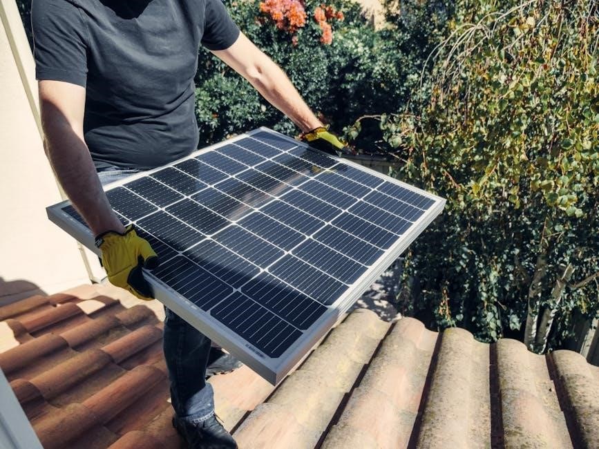
A 12V solar system includes solar panels‚ charge controllers‚ batteries‚ and inverters. These components work together to generate‚ regulate‚ store‚ and convert energy for reliable power supply.
2.1 Solar Panels: Types and Specifications
Solar panels for 12V systems are typically monocrystalline or polycrystalline. They operate at voltages around 22V (Voc) and 18V (Vmp)‚ suitable for charging 12V batteries. Efficiency varies‚ but modern panels often range between 15-22%. They are designed for durability and energy production‚ with specifications tailored for off-grid or RV applications‚ ensuring compatibility with wiring configurations.
2.2 Charge Controller: Functions and Requirements
A charge controller regulates energy flow from solar panels to the battery‚ preventing overcharging and reverse current. It ensures optimal charging and protects the system. For 12V systems‚ PWM or MPPT controllers are used‚ with MPPT offering higher efficiency. The controller must match the solar panel’s voltage and current ratings to ensure safe and efficient operation.
2.3 Battery: Deep Cycle vs. Starter Batteries
Deep cycle batteries are designed for solar systems‚ offering extended discharge capability and longevity. Starter batteries‚ meant for engine starting‚ are unsuitable for deep discharging. For 12V solar setups‚ deep cycle batteries are recommended to ensure reliable energy storage and system performance over time.
2.4 Inverter/Converter: DC to AC Conversion
An inverter/converter transforms DC power from solar panels and batteries into AC power for appliances. Pure sine wave inverters are ideal for sensitive electronics. Proper sizing ensures efficient energy conversion‚ while built-in safety features protect against overloads and surges‚ making it a critical component in 12V solar systems for reliable AC power supply.
Understanding the Wiring Diagram
A wiring diagram is a detailed visual blueprint illustrating the connections between solar panels‚ charge controllers‚ batteries‚ and inverters. It uses standardized symbols and color coding to represent components and wires‚ ensuring safe and efficient system installation. The diagram outlines the flow of electrical current‚ highlights grounding points‚ and includes safety features such as circuit breakers and fuses to protect against short circuits and overloads. By following the diagram‚ users can correctly configure their 12V solar panel system‚ whether for RVs‚ campervans‚ or other applications‚ and troubleshoot issues effectively. Proper interpretation of the wiring diagram is crucial for ensuring all components function together seamlessly and safely.
3.1 Basic Layout and Symbolism
The basic layout of a 12V solar wiring diagram includes solar panels‚ charge controllers‚ batteries‚ and inverters. Symbols represent components like diodes‚ fuses‚ and connectors. Wires are color-coded for polarity and function‚ ensuring clarity. The diagram starts with solar panels as the power source‚ flowing through the charge controller to the battery bank‚ and finally to the inverter or load. Grounding symbols indicate safety connections‚ while arrows show current direction. This standardized approach helps users understand the system’s flow and install it correctly‚ avoiding potential hazards and ensuring optimal performance.
3.2 Color Coding for Wires
Color coding ensures clarity and safety in 12V solar wiring. Red wires typically indicate positive connections‚ while black denotes negative. Green or bare copper wires are grounded for safety. Yellow or orange wires may signify AC power or specific control functions. This standardized system helps avoid errors during installation and maintenance‚ ensuring proper connections and reducing risks of short circuits or incorrect polarity. Always verify wire colors with the manufacturer’s specifications to maintain system integrity and functionality.
3.3 Grounding and Safety Features
Grounding is a critical aspect of 12V solar wiring to prevent electric shocks and protect equipment. Proper grounding ensures all components are safely connected to earth‚ reducing fire hazards. Safety features like short circuit protection‚ incorrect polarity safeguards‚ and surge protection are essential. Always follow wiring diagrams and manufacturer guidelines to ensure safe installations and compliance with electrical standards.
Solar Panel Wiring Configurations
Solar panel wiring configurations include parallel‚ series‚ and hybrid setups to optimize voltage and current. Each method ensures efficient energy flow‚ safety‚ and system compatibility‚ crucial for reliable solar power systems.
4.1 Parallel Wiring for 12V Systems
Parallel wiring connects solar panels to maintain a 12V system voltage while increasing current. Each panel’s positive terminal connects to the next panel’s positive‚ and negatives are similarly linked. This configuration is ideal for charging multiple batteries or maintaining voltage under varying sunlight conditions‚ ensuring consistent energy flow and system reliability.
4.2 Series Wiring for Higher Voltage Systems
Series wiring connects solar panels to increase system voltage while maintaining current. Each panel’s positive terminal connects to the next panel’s negative‚ raising total voltage (e.g.‚ 12V to 24V or 48V). This setup is ideal for higher voltage systems‚ reducing current loss and enhancing compatibility with certain charge controllers or inverters.
4.3 Combination of Series and Parallel Wiring
A combination of series and parallel wiring allows for flexible system design‚ enabling higher voltage and current. This setup suits larger solar arrays‚ balancing voltage and current to meet specific requirements for 12V or higher systems‚ ensuring optimal energy production and scalability for various applications.
Charging and Electrical Connections
Charging and electrical connections involve linking solar panels to a charge controller‚ then to a battery‚ and finally to an inverter or load‚ ensuring safe energy flow.
5.1 Connecting Solar Panels to the Charge Controller
- Ensure the solar panel’s voltage output matches the system requirements (14-18V for 12V panels).
- Use MC4 connectors for secure‚ weatherproof connections.
- Connect positive (+) and negative (-) terminals correctly to avoid polarity issues.
- Verify open-circuit voltage (Voc) is within the charge controller’s acceptable range (e.g.‚ 22V for 12V systems).
- Refer to the wiring diagram for proper terminal connections and safety protocols.
- Disconnect panels before adjusting settings to prevent damage or short circuits.
Always follow the manufacturer’s guidelines for a safe and efficient setup.
5.2 Linking the Charge Controller to the Battery
Connect the charge controller to the battery using appropriate wire gauge to minimize voltage drop. Ensure the battery voltage matches the system (12V). Connect positive (+) terminal to positive input on the controller and negative (-) to ground. Verify voltage settings on the controller align with battery specifications for optimal charging. Install fuses or circuit breakers for protection. Always refer to the wiring diagram for proper connections to ensure safety and efficiency.
5.3 Final Connection to the Inverter/Load
Connect the battery to the inverter using heavy-duty cables to ensure minimal voltage drop. Set the inverter to 12V DC input and AC output as required. Attach the load to the inverter’s AC output. Use fuses or circuit breakers near the battery and inverter for protection. Ensure all connections are secure and properly insulated. Always follow the wiring diagram to avoid short circuits and ensure safe operation.
Safety Precautions and Protection
Ensure short circuit‚ overload‚ and reverse polarity protection. Use fuses/breakers near batteries and inverters. Install low voltage disconnects to prevent battery drain. Follow proper grounding and insulation procedures to avoid hazards and ensure system longevity.
6.1 Short Circuit and Overload Protection
Install circuit breakers or fuses to protect against short circuits and overloads. Use rated components like 30A for solar inputs and 50A for battery connections. Ensure all connections are secure and insulated. Grounding the system properly prevents shocks and fire hazards. Follow specified voltage ratings for components to avoid damage.
6.2 Incorrect Polarity and Reverse Current Protection
Ensure correct polarity by verifying positive and negative connections. Use blocking diodes or DC-DC converters to prevent reverse current flow at night; Check voltage outputs with panels unplugged to confirm proper operation. Secure all connections to avoid polarity reversal‚ which can damage components or cause system failure.
6.3 Low Voltage Disconnect (LVD)
A Low Voltage Disconnect (LVD) protects batteries from deep discharging by disconnecting non-essential loads when voltage drops below a set threshold. This prevents battery damage and ensures system longevity. Properly configured LVDs are essential for maintaining 12V solar systems‚ as outlined in most wiring diagrams.
Parallel Wiring for Multiple Solar Panels
Parallel wiring allows multiple solar panels to be connected‚ maintaining a 12V system while increasing current output. This configuration is ideal for charging larger battery banks efficiently.
7.1 Advantages of Parallel Wiring
Parallel wiring offers several benefits‚ including maintaining a consistent 12V system voltage while scaling current output. This configuration is ideal for charging larger battery banks‚ accommodates varying panel configurations‚ and ensures system redundancy. It also simplifies expanding the system by adding more panels without altering existing connections‚ enhancing flexibility and efficiency.
7.2 Step-by-Step Parallel Wiring Guide
Begin by connecting all solar panels in parallel‚ ensuring positive terminals are linked together and negatives similarly connected. Use appropriate wire gauges to minimize loss. Connect the combined output to the charge controller‚ then to the battery bank. Ensure all connections are secure and correctly polarized to prevent short circuits and ensure safe operation.
7.3 Downloadable Parallel Wiring Diagram PDF
A downloadable parallel wiring diagram PDF is available‚ providing a clear visual guide for connecting multiple 12V solar panels. This resource includes detailed schematics‚ safety tips‚ and step-by-step instructions to ensure a safe and efficient installation. It is ideal for RVs‚ campervans‚ and off-grid systems‚ offering an easy-to-follow layout for beginners and experienced installers alike.
Series Wiring for Increased Voltage
Series wiring connects solar panels to increase system voltage‚ crucial for high-demand applications. It ensures optimal charge controller performance‚ enhances efficiency‚ and maintains safety standards.
8.1 When to Use Series Wiring
Use series wiring when higher voltage is needed for your solar system. It’s ideal for charge controllers requiring increased input voltage‚ optimizing performance in high-demand setups. Series connections prevent voltage drop and enhance efficiency‚ making them suitable for larger systems or when specific voltage requirements must be met for optimal functioning and safety.
8.2 How to Wire Solar Panels in Series
Connect the positive terminal of one panel to the negative terminal of the next‚ creating a chain. This configuration increases system voltage while maintaining current. Use MC4 connectors or appropriate wiring to secure connections. Ensure the total voltage matches your charge controller’s requirements. Always check voltage with a multimeter and consult a wiring diagram for clarity and safety.
8.3 Series Wiring Diagram and Considerations
A series wiring diagram illustrates how solar panels are connected to increase system voltage. Connect positive to negative terminals sequentially. Ensure total voltage does not exceed charge controller limits. Use MC4 connectors for secure links. Ground the system properly and monitor voltage with a multimeter. Refer to the PDF for detailed visuals and safety guidelines. Always follow safety protocols to avoid damage or hazards.
Battery Integration and Management
Battery integration is crucial for storing excess solar energy. Connect batteries in parallel or series to match system voltage. Use a battery management system (BMS) for monitoring and protection.
9.1 Battery Bank Configuration
Battery banks combine multiple batteries to store solar energy. For 12V systems‚ connect batteries in parallel to increase capacity or in series for higher voltage. Proper configuration ensures reliable power supply and system efficiency‚ preventing overcharging and extending battery lifespan. Always refer to wiring diagrams for correct connections.
9.2 Battery Monitoring Systems (BMS)
A Battery Monitoring System (BMS) ensures optimal battery performance by tracking voltage‚ temperature‚ and state of charge. It prevents overcharging and protects against deep discharges‚ enhancing safety and longevity. The BMS integrates with charge controllers and inverters‚ providing real-time data for efficient system management and troubleshooting;
9.3 Maintenance Tips for Battery Longevity
Regularly check battery voltage and ensure terminals are clean and tight. Avoid deep discharges below 50% to prolong life. Store batteries in a cool‚ dry place when not in use. Equalize batteries as recommended to prevent sulfation and maintain balanced cells for optimal performance and longevity in your 12V solar system.
Charge Controllers and Their Role
A charge controller regulates energy flow from solar panels to the battery‚ preventing overcharging. It ensures safe charging‚ optimizes energy harvest‚ and protects the system.
10.1 Types of Charge Controllers (PWM vs. MPPT)
Charge controllers are categorized into PWM (Pulse Width Modulation) and MPPT (Maximum Power Point Tracking). PWM controllers are cost-effective and suitable for small systems‚ while MPPT controllers optimize energy production‚ especially in varying conditions‚ making them ideal for larger or high-efficiency solar setups.
10.2 Setting Up the Charge Controller
Setting up a charge controller involves connecting solar panels‚ battery‚ and load according to the wiring diagram. Ensure correct voltage settings (12V‚ 24V‚ or auto) and configure charging parameters like bulk‚ float‚ and equalization. Always follow safety guidelines to prevent short circuits and ensure efficient energy management.
10.3 Charge Controller Specifications for 12V Systems
Charge controllers for 12V systems must match the solar panel voltage and battery requirements. Look for PWM or MPPT types‚ with maximum current ratings suitable for your panel array. Ensure compatibility with 12V settings‚ efficient power conversion‚ and built-in protections like short circuit and overload prevention for reliable performance and safety.
Monitoring and Maintenance
Regular monitoring ensures optimal performance and safety. Check system components‚ troubleshoot issues‚ and perform routine maintenance to maximize efficiency and extend the lifespan of your solar panel setup.
11.1 Importance of System Monitoring
System monitoring is crucial for ensuring optimal performance and safety. It allows real-time tracking of power generation‚ storage‚ and usage‚ helping identify issues early to prevent malfunctions. Proper monitoring also ensures efficient energy management‚ maximizing your solar setup’s productivity and reliability over time‚ which is essential for off-grid and remote applications.
11.2 Regular Maintenance Checks
Regular maintenance ensures system longevity and efficiency. Check connections and terminals for tightness and corrosion. Clean solar panels to maintain maximum energy absorption. Inspect wiring for damage or wear. Monitor battery water levels and charge status. Verify charge controller and inverter operation. Schedule annual professional inspections to identify and address potential issues early.
11.3 Troubleshooting Common Issues
Identify issues like low power output‚ overcharging‚ or inverter failure. Check for loose connections‚ dirty panels‚ or faulty components. Verify charge controller settings and battery water levels. Test inverter operation and ensure proper grounding. Use multimeters to measure voltages and currents. Address short circuits or reverse polarity promptly to prevent system damage.